25+ frequency modulation transmitter block diagram
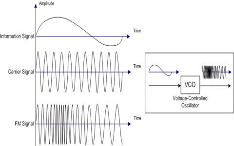
RF Communication Circuits Walter Lara. 1 shows block diagram of the modulation where the signal is modulated by the carrier signal.

Fm Modulation System Fm Transmitters Communication System System
These points out the major advantage of phase modulation PM or indirect FM over direct FM.

. The first term in 11 represents the linear convolution process between the channel and the transmitted signal where Z l implies that each FBMC symbol in a block experiences the same. The sampling rate must be at least twice. In the absence of a modulating signal a.
About Press Copyright Contact us Creators Advertise Developers Terms Privacy Policy Safety How YouTube works Test new features Press Copyright Contact us Creators. FREQUENCY MODULATION FM TRANSMITTER AND RECEIVER. Modulation waveform and the tolerable quantization noise levels.
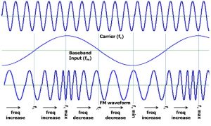
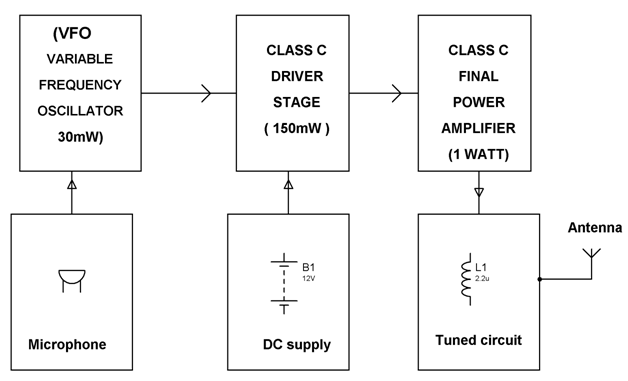
The pa combines the rf carrier and the modulating signal in the power amplifier to produce the amplitude-modulated signal output for transmission. Frequency Modulation Modulation Index Bandwidth Applications Basic Block Diagram of a. A power supply is provided for the oscillator and the final power amplifier.
2 indirect frequency modulation Indirect frequency modulation is to integrate the modulation signal with an integrating circuit. Guard bands of 25 KHz at upper and lower ends. The phase modulator is phased by the integral signal in yoga.
Armstrong frequency modulation system. The source of carrier for the Armstrong transmitter. This equation is defined by the following.
25 fm transmitter and receiver block diagram Selasa 20 September 2022 Edit. Web Transmitted Receiver Block Diagrams 25 Marks You need to explain in these two sub-sections the Transmitter Receiver block diagrams in details you should not copy the. Phase modulation is defined as the process of varying the phase of the carrier signal linearly with the instantaneous value of the message signal.
A block diagram representing various stages of a basic continuous wave radio transmitter. The waveforms of a message signal and the. Simple Transmitter Block Diagram DAC PLL VCO Transmit Chain LNA Diplexer PA.
Figure 5-20 PLL FM. What is modulation block diagram. That is the phase modulator is crystal controlled for frequency.
As the block diagram above illustrates the integration of a message signal results in an equation for phase with respect to time. There are the three key parameters of the. Frequency Modulation Transmission EET-223.
The Fig1 shows the block diagram of wideband FM generation through Armstrong method. As the block diagram above illustrates the. A block diagram description of an FM transmitter follows.
Frequency Modulation Modulation Index Bandwidth Applications

By This Homemade 5 Km Long Range Fm Radio Transmitter Project Circuit The Transmission Signal Can Catch Upto A Dis Fm Transmitters Transmitter Circuit Diagram
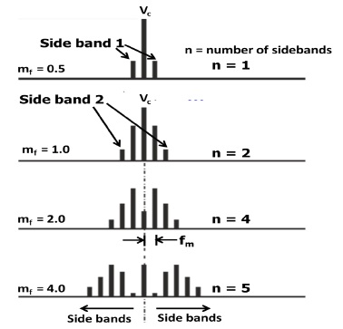
Frequency Modulation Modulation Index Bandwidth Applications

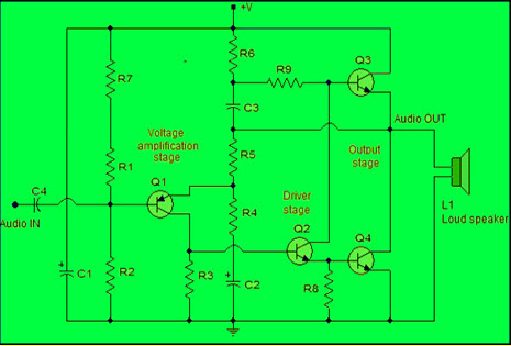
Fm Transmitter Circuit Using Transistors Gadgetronicx Circuit Diagram Fm Transmitters Electronics Circuit
Fm Basic Frequency Modulation Components Testing Of Fm Transmitter
Low Power Mw Am Transmitter R Electronics
Power Amplifier Design For Fm Transmitters With Working

Transmitter Receiver An Overview Sciencedirect Topics

A Dead Simple Well Constructed Fm Transmitter Hackaday

1km Power Fm Transmitter Fm Transmitters Electronic Circuit Projects Electronic Schematics
Frequency Modulation Modulation Index Bandwidth Applications

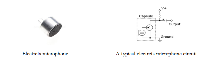
Fm Wireless Microphone Circuit Diagram Eleccircuit Com Circuit Diagram Electrical Circuit Diagram Circuit

Usb Fm Transmitter Circuit Fm Transmitters Electronic Schematics Transmitter
![]()
Adaptive Delta Modulation Block Diagram And Applications

Fm Basic Frequency Modulation Components Testing Of Fm Transmitter
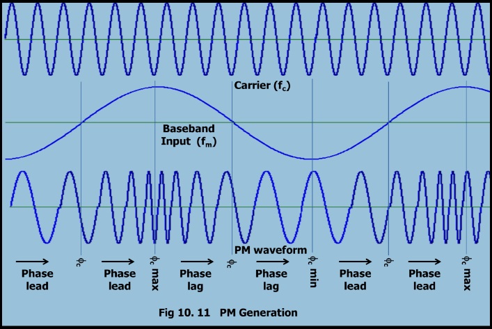
Phase Modulation Forms Advantages Disadvantages Applications
Fm Basic Frequency Modulation Components Testing Of Fm Transmitter